
In one of our previous blog posts we talked about AC motors, the workhorse of modern industrial automation. We learned how they use magnets, electromagnets, and magnetic fields to generate huge amounts of torque to run our industrial processes.
To understand how modern motor control works, let’s take a closer look at how a 3-phase AC induction motor works.
In a 3-phase motor, the stator has overlapping windings that create three pairs of coils. When the coils are energized with a 3-phase power source, each pair of coils becomes a magnetic north and south pole pair that generates a magnetic field.
The rotor in the motor is a magnet itself and so is drawn in the direction of the magnetic field generated by the coil pair.
Each coil pair is offset at an electrical angle of 120 degrees. As 3-phase power enters the stator, each phase of power energizes the offset coils, effectively creating a rotating magnetic field around the stator. The rotor follows this rotating magnetic field and drives our load.

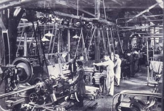
Thankfully, over the past 100 years industrial automation and control have come a long way in keeping operators safe and making automation more efficient.
For the most part, the days of having to manually throw a lever to turn on a motor—and worrying about arc flash from switch contacts—are behind us.
Today we have modern control capabilities that keep operators safe while making operations run more efficiently. So how do we control AC motors in modern times?
 When we talk about controlling AC motors, what we're basically referring to is controlling the ON/OFF state of the motor.
In other words, we’re controlling how our three phases of electricity are delivered to the motor's three pairs of coils. And that’s the basis for modern motor control.
So let’s start at our utility and track the flow of electricity through our motor.
From the utility, electricity enters our plant and is delivered at the circuit breaker. The circuit breaker is where we still have the ability to manually throw a switch to disconnect power. Or the breaker will automatically disconnect the load if too much current is drawn.
From the breaker, our three phases of electricity are wired to some form of motor contact between the breaker and the motor itself. From this point we have three basic methods for starting the motor:
- Direct-on-line starters
- Star-delta starters
- Soft-starter
Method 1: Direct-on-line starters
Direct-on-line starters do exactly what it sounds like they do. We connect all three phases of electricity to the motor and bam! She’s up and running...at about 6-8 times the rated motor current. The reason for this is something called inrush current. Inrush current is the maximum and instantaneous input current drawn by an electrical device when it's first turned on.
In industrial motors, inrush current can range between 4 and 10 times the motor's rated current. This can be a real problem for couplings in HVAC and water/wastewater treatment applications. The motor can push too much volume at one time and literally blow a line somewhere.
An alternative and safer approach is a Star-delta configuration.
Method 2: Star-delta starters
The star-delta starting method reduces inrush current. It does this by switching coil connections between two different positions, the star and delta positions. In the star position, the end terminals of the coils are connected together. In the delta position, the end of one coil is connected in series to the start of another coil.

When a 3-phase power source is applied to coils in a star position, each coil receives a reduced voltage. But in a delta position the coils receive full voltage. Typically, motors are started in the star position and then switched to the delta position for run mode.
Motor contactors are used to switch between the delta and star positions. A timer can be configured to switch between the two settings, or you can set up your control system to do this for you.
Method 3: Soft-starter
Soft-starters use thyristors to gradually ramp up current flow to the motor. With a soft-starter, it’s possible to adjust the torque of the motor to the exact need, whether it’s running or not. (Soft-starters are not the same as a variable frequency drive [VFD], which we’ll cover in a later blog post...because they’re amazing and are getting cheaper everyday.)
So now we know how to safely start our motor.
Most industrial applications (if they’re not already using VFDs) use star-delta starters for motor start applications. So how do we add remote operation capabilities to a motor starter?
That’s where a motor contactor comes into play.
Inside a motor contactor is a coil of wire wrapped around a piece of metal. On top of that piece of metal is another piece of metal that’s attached to an electrical bridge. The bridge connects contacts on one side to the other side. The top metal piece that’s attached to the electrical bridge is called an armature.
Now, when you apply electrical current through the coil in the contactor, you turn the bottom piece of metal into a magnet, which the armature is then attracted to, closing the contacts to run the motor. Then there are springs inside the armature, so that when current is removed from the coil, the armature pops back up. With the armature and coil, we can begin to automate our motor control.
The first thing we’re going to need is a SNAP PAC control system. The SNAP PAC control system consists of industrial I/O installed on a rack and is powered and controlled from a programmable automation controller (PAC). PACs automate the control system for the physical electrical signals that the SNAP I/O is wired to, so the PAC controls real-world devices, like our motor.
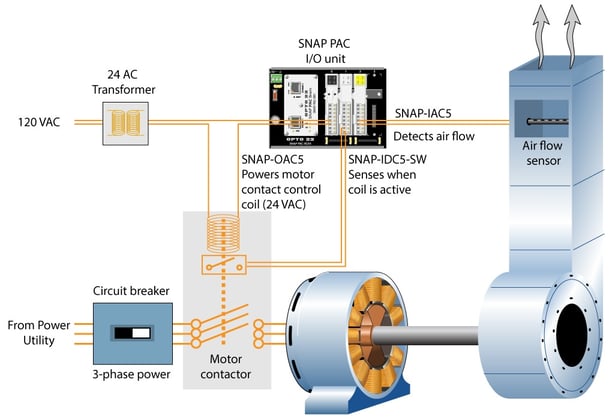
Here’s a diagram of how we might put together a control system to automate starting and running a motor. You only need three input/output (I/O) modules: a SNAP-OAC5, a SNAP-IAC5, and a SNAP-IDC5-SW. And of course we’ll need an I/O rack and a PAC.
Control voltage comes in from the breaker at 120 VAC. We transform that power with our power supply down to 24 VAC (typical voltage for control applications) and wire our SNAP-OAC5 to our motor contactor. We’re using a SNAP-IDC5-SW to sense when the coil is active. This is handy so that in our control program we can write in some error condition detection and handling.
We’ve also added a SNAP-IAC5, wired to an airflow sensor. This is another error condition detection method and can help us track down problems in the system that might not necessarily be related to the motor or the control system, like a blocked inlet or duct.
So that’s an overview of how we’d physically connect components together to automate motor control. For detailed information on programming the control system, check out the SNAP PAC system videos. And if you need detailed information on wiring SNAP modules (as well as part specifications and system architecture), take a look at the SNAP PAC System Specification Guide.
In our next posts we’ll cover more information on VFDs and troubleshooting AC motors. And we’ll put a system together to start adding predictive analytics to your motor control systems.