
That Is the Question.
RS-485 Woes
Whether you work in industrial automation, process control, machine design, or any other industrial application, at some point in time you’re going to run into an RS-485 network. And troubleshooting these networks can be an absolute nightmare.
In fact, let’s all take a moment and thank the network gods for providing us with the 802.3 Ethernet specification and the 8-pin modular connector affectionately known as the RJ-45. Don’t we love the sound of the connector securely clicking into place…
Okay, back on topic.
RS-485 has a lot of strengths. With an RS-485 connection you can run a cable thousands of feet and successfully transmit data across the line, be it a short or long RS-485 line. You can even connect up to 256 different devices together using RS-485 (number of devices depends on RS-485 network configuration, RS-485 drivers, and unit load of each RS-485 node).
And it’s incredibly simple for the most part from a wiring perspective, only requiring a transmit wire, a receive wire, and a signal common wire (YES—please use a signal common wire, grounded at one end only—thanks!). But there are a lot of variables that go into building a robust and reliable RS-485 network.
RS-485 is also a pretty forgiving protocol and may work just fine for years, even if the network is misconfigured. Biasing and termination are used to make an RS-485 network more robust and communication more reliable in certain RS-485 network designs.
If you’re having communication problems on your network, termination and biasing are usually the first place to start in improving RS-485 network communication.
To really understand when and how to implement them, we need to start with an understanding of long RS-485 lines versus short RS-485 lines. And no, it’s not just about the physical length of the wire.
Long Lines vs. Short Lines
You might be surprised to find out that long RS-485 lines and short RS-485 lines don’t entirely correlate to the cable’s length. Long and short actually have more to do with the RS-485 line’s behavior, specifically the time it takes for a signal to travel from an RS-485 transmitter to an RS-485 receiver.
A number of variables can impact how long it takes, including how fast the signals travel in a given type of physical wire, the frequencies of the signals traveling through the wire (think data transmission speed, for example 9600 bps), and, yes of course, the physical length of the wire itself.
If the wires are fairly short and the signal frequency (data transmission speed) is relatively low, say 300 bps, the time it takes for data to be sent and received has little effect on the quality of the data being transmitted. In these types of scenarios, you can typically assume that when a transmitter is enabled or switched on, the receiver on the opposite end immediately sees the signal.
However, if we crank up the frequency to, say, 19,200 bps and extend the wire several thousand feet, we significantly increase the time it takes for the transmitted RS-485 signal to reach the RS-485 receiver.
To understand what’s really happening at the signal level, we need to understand the terms rise time and cable delay.
Rise Time
Rise time is basically how long it takes for an RS-485 transmitter to increase its voltage output to a level that’s considered a valid transmission level, typically 10% to 90% of full range. Its corresponding fall time, the time it takes for the transmitter voltage to drop to a non-transmission level, is typically identical, but it’s a good idea to check the vendor’s datasheet to verify this.
")
Now let’s look at cable delay.
Cable Delay
Cable delay is the time it takes a signal to travel the length of the cable from the RS-485 transmitter to the RS-485 receiver. An electrical signal travels through copper wire at between 124,000 and 140,000 miles a second (wow, that’s fast). This speed is often referred to as the signal’s propagation rate, propagation velocity, or transmission velocity. Basically, it’s how long it takes to actually get the electrical signal through the wire.
To sum up rise and fall time and cable delay, if the cable is short and the rise time is fast, then signal delays don’t really need to be worried about. However, if you start adding thousands of feet of wire with an RS-485 transmitter that has a slow rise time, you may run into problems.
Is it Long or Short?
A general guideline is to determine if the RS-485 line is long or short according to the TIA-485-A standard. In that standard, specifically in supplement TSB-89-A, an RS-485 line is considered long when the signal's rise time is less than twice the one-way cable delay.
So remember that just because an RS-485 line is physically short or long does not necessarily indicate the need for biasing or termination. So when do we need to implement biasing and termination?
When to Terminate RS-485 Lines
Whether an RS-485 driver rise time is slow or fast, or the RS-485 line is long or short, all RS-485 lines can suffer from impedance mismatches, resulting in voltage and current reflections. Typically reflections occur on long lines, resulting in a receiver misreading logic levels. Proper termination prevents reflections, improving data integrity.
When a voltage is first applied to an RS-485 line, current flows through the line (even if the line wires are open). Shortly after reaching the end of the line, the current settles to a final value determined by the series resistances in line, the voltage applied, and termination. The line sees reflected voltages as the current settles if the initial and final currents vary, resulting in possible data integrity issues.
If the data rate is low or cables are short, termination may be unnecessary. As data rates and/or cable lengths increase, which is most cases, termination becomes mandatory.
How to Terminate RS-485 Lines
Terminating a data cable with a value equal to its characteristic impedance reduces reflections and will make your RS-485 network more reliable. Since any device on the bus can transmit at any given time, it is probable that a node in the middle of the bus will transmit, requiring that termination be applied to both ends of the segment.
To correctly terminate a long line, you first need to know the line’s characteristic impedance. You can usually get this information from the cable manufacturer. (There are also much more complicated methods available to figure it out, which are not covered here.)
When adding termination to a line, no more than two resistors should be used, one at each end of the line. For a cable with a characteristic impedance of 120 Ω, the termination resistor should be 120 Ω. In my experience we almost always end up using 120 Ω resistors for termination, because that’s what shielded twisted pair requires. So it might be a good idea to keep a few of those around in the old toolbox.
Choosing the Right Termination
The most popular approach to termination is parallel termination, where you place a resistor across each end of the physical link. Placing it at the end of the line eliminates all reflections, although this approach results in higher power dissipation. Resistive terminators typically have values from 120 to 130 Ω. Although twisted-pair cable impedances can be as low as 100 Ω, a 100 Ω terminating resistor is too low for RS-485 drivers, because two in parallel yield 50 Ω, and RS-485 drivers are not rated for loads below 54 Ω.
Place a termination resistor matching the cable impedance at a convenient location, as close to the end of the RS-485 line as possible. It’s possible that a node attached to the RS-485 line may have terminating resistors built into it as a configurable setting, so check that when adding termination resistors to any line.
In general, termination is a good idea for all long-line RS-485 connections. But some short lines can also benefit from implementing termination, if they have a fast rise time.
Now that you're an official RS-485 terminator, how do we tackle biasing?
Biasing RS-485 Connections
RS-485 is a multipoint communication specification where all nodes share a common two-wire connection (plus one additional wire for signal common). This results in many opportunities for data collisions on the line. On RS-485 networks only one device is allowed to communicate at a time; otherwise data collisions may occur.
In master/slave protocols this is less of a concern, because the master is usually initiating requests and then slaves respond at that time. However, during the time a master or slave is not transmitting, the line floats in what is known as a tri-state mode. Each transceiver supports three different states: on, off (transmitting), or disabled (tri-stated, not transmitting). Only one transceiver at a time can control the link's state with on or off states. All other devices must be in the tri-state mode when not transmitting.
When the line is floating in the tri-state mode, noise on the line can falsely trigger a receiver. To ensure that the RS-485 line is in a defined state when all transmitters are off, we can use failsafe biasing on the line.
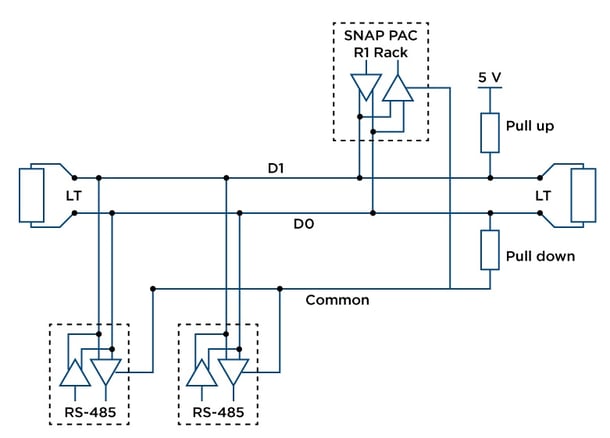
The objective of biasing is to make sure that the RS-485 line remains in a known, non-fluctuating state when no devices are transmitting. Biasing the entire network requires a single pair of resistors: add a pull-up resistor to +5V attached to the +V signal line, and a pull-down resistor to ground attached to the -V signal line. RS-485 networks such as Profibus, Optomux, and DH-485 (see below) typically have biasing resistors at the primary node.
Using biasing resistors in combination with terminating resistors creates a voltage divider. If a node disconnects from the network or there is a break in the network line, the internal fail-safe circuits will hold the inputs at a logic 1.
Common Industrial Protocol Termination and Biasing
Termination and biasing differ depending on the protocol you’re using over RS-485. Here are a few common protocols:
Modbus: Use termination and biasing as described in this blog post.
Profibus: Typically uses external termination outside the node in the form of terminating and biasing resistors located in a DB-9 connector, with dip switches used to configure biasing and termination. The advantage to this method is that all RS-485 nodes are configured the same, and biasing and termination are configured independently to optimize the RS-485 network.
Optomux: With Opto 22 systems in general, biasing is normally done at the host device, like the controller or computer, and it is normally a matter of configuring or enabling biasing (with most Opto 22 RS-485 products, biasing is built in and only needs to be enabled or disabled). Termination is done at the devices at the two physical ends of the link, and again it's typically just a matter of enabling or disabling the built-in termination.
DH-485: Terminating resistors are located at all nodes. However, an external jumper applied at the connector enables termination. This also keeps the configuration in the connector and not inside the node itself.
Now that you’re a pro at RS-485 termination and biasing, don’t forget to check out the programmable automation controllers and serial communication modules from Opto 22.
Ever thought about using a Raspberry Pi as an industrial controller? Check out our Digital I/O for Raspberry Pi at http://info.opto22.com/raspberry-pi-io
Looking for more reference material? The best book I’ve found on all things serial-related is Serial Port Complete Second Edition by Jan Axelson.