In my last blog post I talked about the TCP/IP model and why you should care about it. In a phrase: the Internet of Things (IoT).
With all the recent attention around the IoT, the Industrial Internet of Things (IIoT), and Industry 4.0, I’m sure you’re starting to realize that networking, Internet communication, and network security are going to be important in your job as an automation professional.
 How will automation systems interface with other systems to build the Internet of Things?
When you can’t get that data you need, how do you begin troubleshooting?
Over the next several posts we’ll focus on the TCP/IP model and what happens at each layer when automation systems such as PACs, PLCs, and HMIs communicate over a network. And we’ll talk about troubleshooting communications, layer by layer.
(To read more about the role automation engineers will play in building the Internet of Things, check out Opto 22’s IoT Primer.)
But first, a bit of history to help this all make sense.
In the beginning...there was packet switching
Invented sometime in the late 1960s, packet switching is a communications method used in digital networking. Basically it’s how systems on a network wrap up the data they want to send and forward that data out to other systems on the network and the Internet. Datagrams (basic units of data transfer containing information such as delivery requirements, arrival time, and order of data) are sent across packet-switched networks, allowing hosts to communicate with each other.
Packet switching increases network efficiency and robustness, but most importantly it enables different types of systems to communicate with each other using clearly defined standards. One of those standards is the TCP/IP model, and it’s the basis of the Internet as we know it today. At this very moment, across the entire Internet, multitudes of different types of packets are being sent and received using packet switching technology and the TCP/IP model.
It’s all about the layers
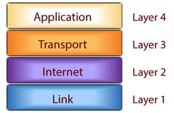
The TCP/IP model is made up of 4 layers. Each layer plays a role in facilitating communication among systems connected to a network. Communication among systems flows from the physical network media (such as Ethernet or fiber optic cable), up through a device (such as a PC), and into an interface, where users or even other systems interact with the data sent over the network.
The 4 layers of the TCP/IP model may be named differently depending on the source referring to them. In this post, we’re going to keep it classy (and by classy I mean RFC-compliant) and center our discussion around RFC 1122, quite possibly one of the most important documents mankind has ever drafted and a great read if you’re having trouble sleeping at night.
The 4 layers of the TCP/IP model are, from the top down:

- Application—Moves data from what you see on your screen to the transport layer
- Transport—Manages communication sessions between hosts locally and on the Internet
- Internet—Routes communication not only on the local area network (LAN) but across the Internet as well
- Link—Physically connects nodes to the network, for example, your Ethernet network interface card (NIC) in your PC
When troubleshooting network systems, it’s often best to start with the lowest layer and work your way up. So we’ll start with the Link Layer.
Link layer
In the TCP/IP model, communication starts at the link layer. The link layer is the point where network hosts (also known as nodes) such as Opto 22 SNAP PAC controllers, your PC, database servers, web servers, and so on connect to the physical network to send and receive data. Each host transmits bits of data to other hosts using electrical signals transmitted on physical media such as Ethernet.
For hosts to communicate at the link layer level they need a physical connection to the network. For example, your PC connects to an Ethernet network using an RJ-45 connector built into the PC’s network interface card (NIC). The NIC has two important components built into it, called a MAC and a PHY. MAC stands for media access control and is the chip-level controller that controls how bits of data are sent onto the network. PHY is the physical transceiver that generates the electrical signal to communicate on the network.
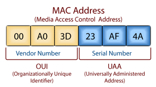
 Each node on the network has a built-in MAC address. This address is burned into the unit (so it’s sometimes called the burned-in address, or the physical address) by the MAC/PHY manufacturer.
As you can see in the image, the MAC address format is a group of six hexadecimal numbers; the first 3 are unique to the hardware manufacturer, and the last 3 are assigned to the specific device.
You can think of an Ethernet address as the unique address used to locate that specific device on the local network. But note that Ethernet is not a routable protocol. So for a host to communicate beyond its local network—for example, on the Internet—it needs to use a routable protocol such as IP, which lives at the next layer up, the Internet layer. We’ll cover these in a later blog post.
Troubleshooting at the link layer
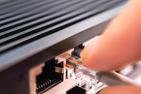
Troubleshooting link layer issues is typically straightforward. To start troubleshooting a communication issue, first check the host’s link light. This light should be on the host’s NIC, typically close to where the Ethernet media is connected. For example, the link light on a SNAP PAC controller is right on the Ethernet jack.
Unplug the Ethernet cable from the RJ-45 and check to see if the link light goes off. Plug the cable back into the Ethernet jack and see if it goes on. If it doesn’t, you may have one of the problems below.
1. Bad Ethernet port on the Ethernet switch
This could be caused by a number of things, including:
- The Ethernet port on the switch may have been disabled by your IT Department.
- The port on the switch may be physically bad.
- The port on the switch may be set to a specific Ethernet speed or duplex mode that the host doesn’t support.
- The autonegotiation of speed and duplex mode between the host and switch may have failed. Ask IT to hard-code the switch port to the speed and duplex the host supports.
Try another switch port and see if the problem follows the host side connection or the switch port.
2. Bad Ethernet cable
One of the most valuable tools you can have when troubleshooting a link layer issue is an Ethernet cable tester. You can pick one up fairly cheaply and it can save you hours in troubleshooting.
- The number one cause of a bad Ethernet cable is a bad locking tab on the RJ-45 connector. Make sure it seats firmly. If the tab is missing, cut the connector off the cable and recrimp with a fresh RJ-45 connector.
- Use a different cable. Try that cable with a known good working host. See where the problem follows.
- Make sure you’re using an Ethernet cable and not some other cable that just happens to have an RJ-45 connector on each end.
- Check whether the Ethernet cabling is wrapped around something that’s putting out enough electromagnetic interference to disable communication through the cable, like an air conditioning unit. Or maybe it’s routed right next to a microwave.
- Check cable length. Ethernet is spec’d for 100 meters or about 300 feet.
3. Broadcast traffic storm
Watch the network traffic LED. If it’s completely solid there may be a broadcast traffic storm on the network. This will reduce network performance and is easy to track down with a network analysis tool like Wireshark, www.wireshark.com.
What's next?
Check back soon for the next blog post, where we’ll talk about the Internet layer. In the meantime, take a look at Opto 22’s IoT Primer to learn more about industrial automation’s role in the Internet of Things.

