
This technical tip post covers the history and challenges of connecting RS-232 serial devices together.
The nice thing about standards is that there are so many to choose from. Like every profession, industrial automation has a veritable cornucopia of standards we need to be aware of. RS-232 is no different or special in that regard.
Let's take a look at the history of this hardware communication standard and use that as a springboard. We'll take a look at how modern microprocessor technology can be adapted to this very commonly used data communication standard in the industrial automation world.
Fun fact: The "RS" of RS-232 stands for "Recommended Standard" and sure enough, its standard number is two hundred and thirty-two (232).
Low transmission speed, short cable length, large voltage swings required, bulky connectors, no multipoint capability—so why is it even still a thing? Because it has been around since the 1960s.
It first got traction as teletypewriters were connected to modems. I'm sure no one ever imagined that it would be used from those days all the way to devices like GPS receivers.
Since the range of devices that adopted RS-232 varied greatly, so did the connector pinout, giving rise to a healthy market for breakout boxes and cables of all varieties.
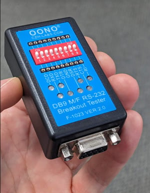
Who remembers using a breakout box similar to this?
As you no doubt know, computers only work with binary ones and zeros. All an executing piece of software is doing is just moving around and understanding these ones and zeros.
Serial data is just the same. We need to convert the RS232 data stream into a series of ones and zeros that the computer software can understand.
Back in those teletype days, binary and digital communications were still getting established, and the way engineers talked about those ones and zeros was by calling them space for a zero, and mark for a one.
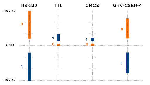
Mark/Space Voltage Levels
Logic zero (space) is signified by any voltage between +3 and +15V DC
Logic one (mark) is signified by any voltage between -3 and -15V DC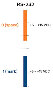
An open-circuit RS232 cable is allowed to have a voltage of up to 25 VDC. Usually, the mark/space voltages were grouped. For example, any voltage swing between ±5 or ±12 or ±15 was permitted as part of the standard, and usually, one of those three groups was the most widely adopted for any given device.
Those mark/space voltages are always in reference to the ground wire. If the two bits of communications equipment are far enough apart, or one has a faulty power supply and so the grounds are at a different potential, then a ground loop may exist, offsetting the mark/space voltages and thus causing communication errors.
With that quick history of RS-232 in mind, let's now take a quick look at the two broad types of electronics that most of the industrial world uses or comes in contact with.
TTL
Mechanical teletypes grew up and became smaller and lower power thanks to a breakthrough in Transistor-Transistor Logic (TTL) integrated circuits (IC). TTL started out life using zero to five volts DC. So straight away, we can see an issue with our RS-232 standard—there is no negative voltage for our mark (or one) part of our data transmission.
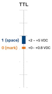
The other curveball that came from moving to TTL is that the format uses zero volts for a space and positive volts for a mark, inverted from what RS-232 is expecting.
So not only do we have a voltage swing that is outside our standard, but the mark/space voltages are incompatible as well.
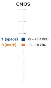
CMOS
TTL quickly grew up and was a bit too power-hungry (in the current-draw sense of the word), and so CMOS (Complementary Metal Oxide Semiconductor) came to our technological rescue. CMOS still used low volts for space and high volts for mark, but the voltage became 0 and 3.3.
Caution: if you put TTL 5 volts DC where CMOS was expecting 3.3 volts DC, well, that would be the last time you make that mistake with that device.
A well-known computer that uses CMOS for its serial port is the Raspberry Pi.
An interesting quirk about TTL and CMOS is that you can safely use a CMOS output to drive a TTL input, but not the other way around. In other words, if you have a CMOS transmit data output pin, it can be connected to the TTL serial data input pin. The serial data will be understood and decoded by the software since the CMOS 0 to 3.3 V can safely send 0 and 1 to a TTL input. But if the TTL needs to send data back to the CMOS device, there will be smoke as the TTL 5V will simply destroy the 3.3 V CMOS input.
Confused? Let's add one more serial device, and then we will get to fixing this mess of standards the best we can.
GRV-CSERI-4
Opto 22 makes world-renowned industrial automation hardware in its Temecula, California factory—yup, 100% made in the USA!
The groov EPIC platform allows many different I/O signals to be processed via different plug-in modules. The GRV-CSERI-4 module provides four independent, isolated serial channels. They can be configured for RS-232 or RS-485 (a standard for another blog post, perhaps).
-4.png?width=400&height=400&name=GRV-CSERI-4_LidCloseOpen_800%20(1)-4.png)
TIP: The groov serial modules can only be used in the first four chassis slots, thus allowing up to sixteen serial ports per rack. Opto 22 has chosen to use the very common mark/space voltages of ±12V DC for the groov serial module.
Quick hardware recap
- RS-232 uses negative volts for a logic one; the voltage commonly swings between ±12V DC
- TTL uses positive volts for a logic one; the voltage swings between 0 and +5 VDC
- CMOS uses positive volts for a logic one; the voltage swings between 0 and +3.3 VDC
RS-232 is used on a vast array of industrial hardware products, TTL likewise is pretty robust and widely used. CMOS is commonly used in low-power devices and for applications that might use battery power. Perhaps 3.3 VDC is the future of industrial automation devices?
Regardless of the future, if we need to connect any of these devices together today, right now, what are our options?
MAX232 Level Converter
I'm pretty sure the problem of converting standards has been around since the first two standards for the "same" thing came into the world. Back in the '60s to '80s, RS-232 needed two power supplies to generate both the positive and negative voltages it specified, which added cost and bulk to any device that supported it.
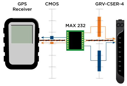
Two guys came together in the mid-80s and designed a chip they called MAX232 that used capacitors and charge pumps to generate ±7.5 volts from a single +5 VDC. Note how ±7.5 volts fits inside the "Recommended Standard" 232—and it doesn't just generate the required bipolar voltage, but also inverts the mark/space polarity. This one chip really changed the cost and complexity of interfacing TTL and RS-232.
Years later, we now have even more flexible versions of that chip that will convert either 5V or the 3.3 V of a CMOS device up to a voltage that devices like the groov EPIC serial module will more than happily chat back and forth with, without releasing the electronic smoke.
When and which converter?
You will need to read the datasheet very carefully for the RS-232 device(s) you want to communicate with. Simply scanning the sheet and seeing ‘RS-232’ is not enough these days. You will need to verify what aspect of the standard and, specifically, what voltage your device requires on both ends.
Once you know what voltage, you will know which converter you need to use.
The MAX232 chip can be used on a custom circuit board or as premade modules, and both cased and uncased assemblies can be purchased from a wide variety of electronic parts manufacturers. Some come with serial connectors attached; some are left to you to solder or attach the connecting wires from the two serial devices, which can be useful in OEM applications.
TIP: If you are just using TTL and CMOS, in a pinch, you can use either a voltage divider made of two resistors or a series of diodes to drop the TTL voltage down to safe CMOS levels.
Another tip: If you never want to transmit to a device, for example, a GPS receiver where you just need to receive a stream of latitude and longitude from the device, you only need to consider the received data voltages, not the transmit voltages. For example, if the GPS is a CMOS device, then the 0 to 3.3 VDC will send its data to a TTL input just fine. No converter is needed.
But if you want to use the same GPS with a groov serial module, then you will need a level converter for the GPS transmit data to not only invert the mark/space voltage but also lift the 0 to 3.3 V from the CMOS level to ±12 VDC for the EPIC module. You will also need to ensure that the level converter you choose is compatible with the 3.3 VDC from the GPS (in other words, don’t use a 5V TTL level converter).
As industrial automation application engineers, it's our job to figure out how to connect different devices together so that the whole process works seamlessly today and well into the future. I hope this short primer will help you not only today, but going forward as new "standards" are introduced for the tried and tested Recommended Standard two hundred and thirty-two.
Cheers Mate.
-Ben