
What looks like a donut, but you can't eat it, yet it still gives energy?
Clearly, I’m not very good at riddles, so I’ll cut straight to the answer: a current transformer, or CT.
CTs are a critical part of any electrical load monitoring system, so let's take a look at how they work, the different types, how to size them, and lastly, two important aspects of installing them.
Why we need a CT
We often need to measure very high currents, be it for an entire site, a building, or a piece of equipment. This current might be in the order of 50 to 5000 amps. How to measure that safely and accurately? That’s the job of the CT or current transformer. It can convert a large primary current to a smaller current that can be safely measured. And it looks like a donut.
How CTs work
The CT takes advantage of the fact that there is an alternating magnetic field around every cable that carries an AC current. (While you can get DC current sensors, that's a topic for another post.) If we place the source or load cable through the center of our donut, we get a magnetic field induced in the core that is proportional to the current flowing through the cable.
Then we simply wind a much smaller wire around that core. The exact number of windings depends on the ratio we are looking for to get a smaller current that is directly proportional to the load current.
A picture is worth a thousand words, so what does this look like?
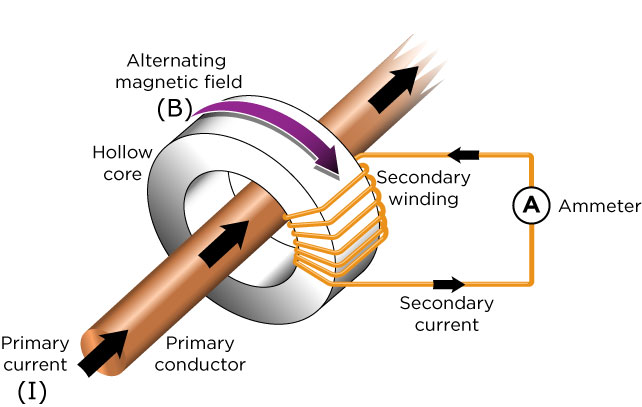
In the above image, the primary copper conductor carries our load voltage and current. The hollow core donut picks up the alternating magnetic field, and the secondary winding then produces the reduced current that matches the current in the primary conductor.
Now that we have covered the basics of how a CT works, we can start to see a bit of a problem…
The secondary current is a short circuit through our ammeter, a device with very minimal resistance (in Ohms). It's just enough resistance to develop a few millivolts for our measuring device. But what happens if we disconnect our ammeter? The secondary winding attempts to drive its current into that open circuit, and thus you might get a very high voltage on the CT wires. Depending on the CT turns ratio, it could be a very high voltage–high enough to be very dangerous to human life. These 0 to 5 amp CTs carry very strong warning labels about just that danger.
WARNING: Never, ever disconnect any sort of current output CT while the load is live.
This, of course, begs the question: Is there a way of configuring a CT that is safer?
Fortunately, yes. By placing a “burden resistor” in the CT, you can change the current output to a very small voltage output. This small AC voltage is proportional to the load current with none of the dangerous side effects should you disconnect the CT secondary while the load is powered up.
Here is a diagram of the internal makeup of a voltage output CT:
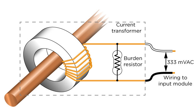
You can see that the burden resistor is located inside the CT, and as a result, the small voltage on the CT output is safe to touch at any time. Note also that the burden resistor value is chosen to match the primary, or load current.
This brings us to the next step in our journey, choosing the right type of CT so we can correctly size it for our purpose.
Types of CTs
Broadly speaking, there are two and a half types of CTs that are commonly used:
- Solid core or bus bar
- Split core
- Rogowski (rope) coils
Solid core and bus bars can be grouped together; just the shape differentiates them. Split Core we'll talk about in a moment.
Rogowski, or rope coils, generally require you to supply an integrator, or amplifier, and an associated power supply. While perhaps more convenient to install, their higher cost and extra equipment wiring puts them in a different class from our main two types.
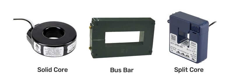
- Solid Core is just that, a solid donut. The load or source cable must be passed through the center of the coil. This requirement makes them best for greenfield installations. The load must be totally powered off, and the inner diameter of the CT must be sized to be no more than twice the diameter of the load cable.
- Bus Bar CT is the same as the solid core, just a very different shape to fit around the wide bus-bar style of an electrical distribution board.
- Split Core can be unclipped on one end, placed around the load/source cable, then clicked shut. For safety, the load should be powered off when installing the CT, but the split core style saves it from being totally disconnected. A lot of electrical terminations have a limit as to the number of times they can be removed or installed, and their torque ratings must be carefully adhered to as well. Using a split core mitigates all of these requirements and concerns.
Ok, so we have decided what style of CT we require. What are the pros and cons of a 0-5 amp output compared to the safer 0.333 VAC output style?
Current or Voltage Output?
0 to 5 amp CT output wire runs should be kept as short as possible because they are carrying up to 5 amps. Any extra length of cable will have an impact on accuracy. These current output CTs have lower accuracy at low load currents. As mentioned, they should never be disconnected when the load is powered. You cannot wire their output in parallel with more than one measuring device, and depending on whether the measurement device is fully isolated or has a common ground, you may or may not be able to wire the CT in series with the different measuring devices.
0.333 VAC CTs are generally lower cost as the wires do not have to be as thick (they’re not carrying up to 5 amps). They are more accurate at low currents with respect to their rated output. Their output wires can be extended a moderate distance (up to 100 ft), but you should ensure that the gauge of wire throughout the distance is similar and that the wires have a similar twist to the wires on the CT. Lastly, the 0.333 VAC output can be paralleled up with more than one current measuring device, with only a very small loss in accuracy.
New or existing CT?
If you have existing CTs already installed, in some ways, your type choice has been made for you. Unless new features or changes are required, it may be better to go with the type you currently have, assuming they’re compatible with the measuring equipment you plan to use.
For an existing installation, here are some questions you need to answer going in:
- What’s the primary current of the CT (for scaling purposes)
- What’s the output type (not all current types are 0 to 5 A, and not all voltage types are 0.333 VAC)
- Is the installation Delta or Wye (so you can configure the power meter correctly)
- Where’s the termination point of the existing CTs
When it comes time to move the output of the CTs, if it’s a current type, be sure to fully power down the load before disconnecting them.
For a new installation, here are some things you need to know:
- The maximum and typical amps the load pulls from the power system (TIP: Check the load circuit breaker or the equipment plate on the device itself, or look in the manual.)
- The wire size feeding the load (where you want to install the CTs). This is important as you need to ensure that the wire will fit through the CTs and that the inner CT size is not more than twice the load cable diameter. Accuracy suffers if the CT is needlessly oversized.
- The type of CT you want to install: solid, split, or bus.
- The signal type you want to use. Usually, for a new installation, a 0.333 VAC is the better choice.
CT Sizing: Maximum vs. Average Current
CTs don’t blow up or become damaged if they momentarily are pushed beyond their maximum current. Why does this warrant a mention? Often, heavy loads or inductive loads have very large, short-duration currents. Should you size your CT for those very short, but very large currents, or for the average machine running current?
If you are interested in accurately measuring these large in-rush currents, then sure, up-size the CT. If the machine only starts up once a week or once a month and spends the rest of its time humming along, then size for the more typical load. The reason to think about this is to determine where you want your best accuracy. A 150% overloaded CT, as I said, won't stop working; it will just be saturated and not accurately show the true over-current value. Likewise, a 500 amp CT is not going to be able to accurately show very low currents (typically less than 5% of rated current).
Cable Size Matters
Since the CT has to accommodate the load in two ways–sizing the maximum current expected and fitting the cable through the CT with no more than twice the wire size–you need to pay attention to the load wiring.
First up, it's somewhat common to supply the load with parallel conductors. This is typically done for cost reasons, since smaller diameter cable often costs less to purchase and install. It can also be woven in and around existing equipment and cableways faster than a larger, heavier, single-core power cable.
If physically possible, the CT should clip around all the conductors that are powering each phase of the load. If this is just not possible, then the CT can be clipped around one or more of the conductors and notes made so that the scaling can be adjusted for a full-scale reading. (The electrical engineer who designed the multi-cable run would have anticipated that all the parallel conductors would carry very close to the same current each.) For loads with one cable per phase, it is simply a case of making sure the outside cable diameter fits through the CT.
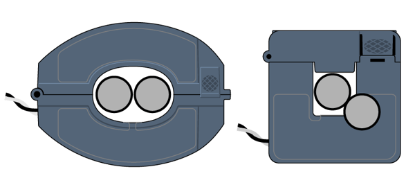
It’s worth noting here that for multi-cable installations, some Continental Control Systems CTs have an oval opening to better accommodate two cables.
Here is a scale drawing to show it in action:
If you need a quick cable sizing table, this page lists the most common sizes, cross-referenced with CT opening sizes.
Installing CTs
Let's be clear: In all cases, only a licensed electrician should install current transformers and meters. All NFPA and NEC rules should be followed.
When it comes time to actually install the three CTs, the most important thing is to ensure that they are all facing the same direction. Most CTs are marked with an arrow or label indicating “This side to source” (or “This side to load”).
Two main installation parameters that really must match up:
1. All CTs face the same way, and
2. Each CT matches its phase voltage. That is to say, the CT for Phase A must be clearly marked so that the voltage tap for Phase A can be matched with it on the power monitor, and so on. Trust me, there’s nothing worse than having one or two CTs installed backwards, and one or two of the CTs wired to the wrong phase voltage. It's very confusing to both humans and energy monitoring devices!
Ok, let's summarize all we’ve said in far fewer words! (TL;DR):
- CTs work by supplying a proportional output voltage or current to the current flowing through the cable it is clamped around.
- There are two main physical types: solid core and split core.
- There are two main output types: 0.333 VAC and 0 to 5 amps.
- Never disconnect the 0 to 5 amp CT when the load has power.
- When installing CTs, make sure they all face the load or they all face the source. Make sure each one is clearly marked so the Phase A CT can be matched with the Phase A voltage, and so on.
Power = voltage x current.
With the right-sized CTs installed correctly, your power and energy data will be accurate from the moment the load is powered up.
For more information about Opto 22’s energy monitoring unit, groov RIO EMU, you can review my previous blog here:
https://blog.opto22.com/optoblog/measure-live-power-and-energy-consumption
Cheers mate,
-Ben